Category Archives: Woodworking

The Value of "Clean Modeling"

David Heim is a veteran book and magazine editor specializing in woodworking. After a 28-year career at Consumer Reports, he moved to Fine Woodworking magazine. David has been writing about and teaching SketchUp for over four years, and says he never begins any project until he has previewed it in SketchUp first. This is one of several upcoming SketchUpdate guest posts from David on modeling principles for woodworkers.

I first heard the phrase clean modeling from Dave Richards at 3D Basecamp 2014. As Dave explained it to me later, clean modeling is a simple concept that basically means, “learn to sweat the small stuff.” If the model isn’t “clean,” small flaws could interfere with the changes you or someone else may want to make in the future. Let’s take a closer look at clean modeling principles via a Shaker trestle table I did a few years back. It looks pretty good, right? Actually, it’s a good example of why clean modeling is important.

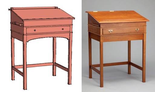
Although this model of a Shaker table looks pretty good, it actually contains a number of flaws; finding and fixing them is what clean modeling is all about.

Missing Faces. I thought enough of the trestle table model to share it on the SketchUcation woodworking forum. Someone quickly cut me down to size, pointing out that my turned legs were missing faces. It’s a good thing no one looked closer. In fact, there were several problems with the model. Let’s begin with the missing faces. It happened because I was working with small geometry at a 1:1 scale. I could have saved face, so to speak, if I had scaled up the leg profile before extruding it.

The blue areas (left side) show where faces were not created properly. The right side shows the successful result of the scaled up Follow Me technique.

You can heal these faces by tracing over some of the edges with the Line tool, but it’s better to scale up certain components before using Follow Me or running Intersect Faces. Dave Richards typically copies a component to be extruded or intersected, scales it up 100x or even 1000x, and then edits the copy. After that, he deletes the copy; the original will show the edits properly. Generally, I’ve found this scaling method ensures a model won’t wind up with small missing faces.

A closer look. Inspecting the bottom of the arched feet reveals more small problems. If I run ThomThom’s Solid Inspector extension, it shows me a stray line at one corner. It’s only about 1/64” long, but it shouldn’t be there. The same goes for a sliver of a stray face on the opposite corner. Extraneous lines and faces like these can pop up sometimes when performing certain tasks — like Intersect Faces mentioned above. These little lines are hard to see, of course. I could say, “So what? No one will ever see them.” Maybe, but I need to get rid of them if I want a clean model.
Ed. Note: ThomThom recently released Solid Inspector². Also, try “StrayLines.rb” from www.smustard.com.

The Solid Inspector extension reveals a minuscule stray line at the base of the foot. This extension is a useful tool for identifying extraneous geometry that could be erased.

Orient faces. Obviously, visible faces must be oriented properly. But the same goes for faces that aren’t meant to be seen: the sides of holes, recesses, mortises, and the like. As you create those elements, take the time to be sure the correct face is showing. If a surface is facing the wrong way, you can right-click on it and choose Reverse Faces.

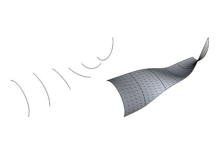
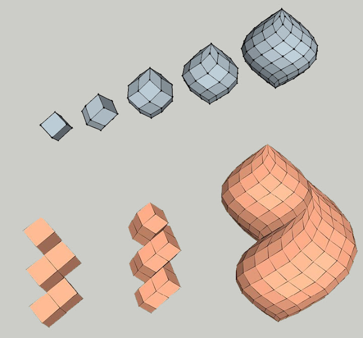
Soften/Smooth curved faces. Often, when you Push/Pull a shape that results in a curved face, you’ll also create edges separating the facets of the curve. You can hide those edges, but the face will still look faceted. It’s better to eliminate the edges with the Soften/Smooth Edges technique.

Hiding the edges on a curved face leaves the surface looking faceted (middle object). For a truly smooth face, use Soften/Smooth Edges.

Set component axes. If a component doesn’t perfectly align to the axes, be sure to set the axes when you create the component. This is especially important if you’re planning to use the CutList extension. It relies on the size of the bounding box to reckon the size of the component. An oversized bounding box will lead to inaccuracies in the cutlist.

Clean-up. Finally, reduce the file size: purge unused components, use multiple copies of components instead of numerous groups, and compress textures. ThomThom’s CleanUp³ extension helps expedite this process. If my advice strikes you as too obvious, that probably means your models are pretty clean already.

Guest authored by David Heim

Fabbing with friends: a WikiHouse for World Maker Faire

When we first heard about WikiHouse, we knew we wanted to build one. When WikiHouse’s co-founder gave an inspiring Ted talk this past May, we were inspired to build one. And when we read the WikiHouse modeling standards (make groups, use layers!), we knew that we just had to build one.

So as we sat down with the WikiHouse team this summer and talked about how we could collaborate for World Maker Faire, our goal was a no-brainer: design and build our own WikiHouse in just over a month.

The SketchUp WikiHouse for World Maker Faire. View more photos of this project here.

Kicking off the project, it was quickly evident that between the SketchUppers and the WikiHouse’rs, there were more than enough architects to go around. Aside from the reality that no one on the team had a CNC router in his garage, we knew we’d need a project partner with tons of CNC experience — and one who wouldn’t laugh off the idea of hammering together a thousand cut pieces in the middle of Maker Faire.

Enter our friend Bill Young over at ShopBot Tools. We’d been itching to do a project with Bill since he caught us spreading saw dust all over Maker Faire Bay Area earlier this year. Bill’s practical experience with wood selection, tolerances, and project planning are nicely measured by his ability to engrave anything (onto anything) while generally believing that most things are possible. With the right mix of optimism and practicality, we started trading SKP’s back and forth, hashing out the trade-offs in various design concepts.

Concept 1: A custom tarp could be tricky, and would we even hear ourselves over a CNC in one bay?
Concept 2: Using ‘Add location,’ we noticed the lookout would showcase a cozy stretch city highway.
Concept 3: We were charmed by an iconic design with exposed sections, but this required too much wood and time.
The Constructible Model: Just right with all the right hooks, tabs, and S-joints.

With an ‘as-built’ SketchUp model set and 160 sheets of plywood sitting in Bill’s shop, it was time to derive cutting sheets and turn up the ShopBots. (Note: if you’re looking to prep your own model for CNC, the free WikiHouse plugin for SketchUp turns grouped geometry into neatly laid out cutting sheets).

Soon after we began cutting, it became clear that our two central constraints were time and lumber. Thankfully, our design and tools were well-suited to these pressures. The WikiHouse design standards call for modular elements that could easily be added, subtracted or adapted — and because WikiHouse uses SketchUp as a platform, making in-progress changes was painless and quick. With a quick pivot for build phasing (agreeing what to cut next based on how much wood and time remained), the sawdust started blowing and the sheets started piling.

Ply piles in progress: only a small accumulation of the full project. See more photos from our cutting phase.

Some 1,150 cut pieces later, we are on our way to New York City after a fantastic month of collaboration between architects in the U.K., software engineers in Colorado, and woodworkers in Virginia. When we reach World Maker Faire, we’ll be joining forces with friends from the SketchUp community to show what open design tools, open design platforms, and a bit of courage can accomplish in just two days.

The right tools for the job: custom cut and engraved wiki-mallets for World Maker Faire.

Didn’t make it to World Maker Faire? Follow the build progress.
Want to see more photos of our project to date?
Watch a timelapse of the SketchUp WikiHouse build.

Posted by Mark Harrison on behalf of the SketchUp Team

SketchUp Pro Story: Bob Lang, Woodworker

Robert W. Lang is executive editor of Popular Woodworking Magazine, and the author of several books including “Woodworker’s Guide to SketchUp.” Bob blogs about Woodworking and SketchUp at his website ReadWatchDo.com. We asked him to tell us a little bit about his process and why he uses SketchUp Pro.

Building furniture is a rewarding process. Most of the challenge is problem solving; time in the shop is always in short supply and quality materials aren’t cheap. Good problem solving at the start allows a more efficient build and prevents costly mistakes.

The efficiency of SketchUp means I don’t spend as much time designing and planning as I used to, which gives me more hours in the shop. Those shop hours are also better because I have a reliable reference that answers almost any question that might come up while I build. (Except for “where did I leave my pencil?”) I can concentrate on the physical work without being sidetracked with an hour or two of head scratching to solve a design or engineering problem

Early in my career, I fancied myself a designer and vowed to only create original designs. Then one day I read something from Gustav Stickley to the effect that if you wanted the ability to design new work, you needed to thoroughly understand everything that had been done before. Twenty-five years later, my work is mostly reproducing designs from the Arts & Crafts period of the early 20th century. This chair (below) is a Stickley piece, and despite its simple appearance there are a lot of subtleties to the overall design. These quirks are what make this furniture intriguing—the closer you look, the more you find.

When I’m planning a reproduction, I work a lot from photographs. My process is mainly the same one I used years ago with pencil and paper. Importing a photo, scaling it to actual size and measuring the photo on screen are far easier (and more accurate) than staring through a magnifying glass and using a proportional rule.

If possible, I work from photos I’ve taken myself; these are different than photos taken for publication. I’m looking for information, and the best source of that is a straight-on view. I’ll do some things in Photoshop, sometimes correcting for lens distortion, but mostly I adjust the image to make it easier to discern details.

After I import a picture into SketchUp, I scale it so that parts I can measure with the Tape Measure tool match known dimensions. I place the images on a separate layer, so I can easily turn them off and on as I build the model. I usually build the model near the photos, but for some parts I work on top of them. To get the outline of the corbel under the arm, I traced the shape on top of the image, then extruded it to the proper thickness with Push/Pull.

I import photos into SketchUp and scale them to a known dimension. Sometimes I model next to the photo, and sometimes I trace directly over the photo.

Sometimes the photo will reveal something I’d rather not see. The next image is from early on in the process, right before I discovered that the lower rail between the front and back legs isn’t parallel to the floor, as I have it in the model. That slight angle adds a lot to the appearance of the finished chair. It’s the chair’s way of saying “Come and have a seat!”, but it makes building the side assemblies considerably more difficult. Instead of five identical vertical slats, each one is a bit longer than its neighbor. Additionally, the shoulders of the tenons have to be cut at an angle rather than square.

With the photo available within the model for reference, I can check dimensions and details while I work. In this case I realized my first attempt missed an important but subtle detail.

Eventually, I have a model that I’m happy with; I consider this the halfway point of the process. The second half is extracting information from the model. Everything I want or need to know about every part of this chair is there on screen. Now the task is to pull out the information I need (or want to show someone else) and to put it a manageable form.

In the shop I tend to spread out until the project I’m working on covers every available horizontal surface. I follow much the same process when working in SketchUp: I make copies of the entire model (or portions of it) off in empty space somewhere to serve different functions. I create scenes for each of these views, with layers for dimensions, so I can export or print only that portion of the model. If you back up and look at everything, it’s pretty chaotic.

Zoom Extents makes it look like I’ve made a horrible mess, but I generated several scenes in a short period of time, each showing important details by copying portions of the model and moving them into empty space.

That said, each scene has a lot of value; there are a number of ways scenes can be used. In my work on books of measured drawings and for Popular Woodworking Magazine, scenes are exported to Adobe Illustrator to use for two dimensional drawings (plans, sections and elevations) or three dimensional exploded views.

This is a typical Scene that I will print and take to the shop to use as a reference for each part of a complex assembly. The model contains precise information about every part, and if I forget to print a dimension I’ll fire up the laptop, open the model for a closer look and measure the parts in the model.

For a project build video, I exported an animation of several scenes and used that clip in the finished video to explain the construction process. For my own use in the shop, I print 3D views of groups of parts and stages of the process for reference. For the side assemblies of this chair, I printed exploded views as well as details such as the image of the leg joinery. In SketchUp, it doesn’t take long to create these extra views. So far, when I wonder “Can I do this with the model?” the answer has been, “Yes I can, it works very well, and it doesn’t take very long”.

Instead of standard cutlists, I create views such as this to accurately lay out the parts. It might take 5 minutes to drag each leg out of the Components window and add dimensions, and it saves hours in the shop. It’s surprising how close this is to having real parts to refer to.

One unexpected benefit of using SketchUp is that it turns out to also be a great tool for teaching woodworking. Unlike a valuable antique, a 3D model can be taken apart to study how it goes together. When I teach a class on building a piece for real, one of the main lessons is the sequence of doing the work. This is a crucial skill for successful building; knowing which parts to layout and cut first, how those first parts affect the following parts, and how to group parts together in sub-assemblies to make the final assembly simple. With a good model, an inexperienced builder can work all of that out before getting to the shop, learn the lesson in less time and not risk wasting valuable materials or shop time. The boost in confidence from this makes a significant difference in both the quality of the time spent building and in the quality of the finished product.

Reproducing a Stickley Morris chair is a lot of work, but there is a built in reward when the job is done.

Over the last 30 years, I’ve invested a considerable amount of money in tools to do my job. A large portion of that has been spent on computer hardware and software. Looking back, the best investment has been the money I spent on SketchUp Pro. I started using SketchUp thinking it might be an effective drafting tool, but it’s turned out to be much more than that. This simple-to-use software program is the best thing I’ve found for all phases of design, engineering, planning and communicating.

Organic modeling made simple with Curviloft

The process of extruding one 2D profile such that it ends in another, different 2D profile is often called lofting. There’s no easy way to do this in plain ol’ SketchUp, but there are plenty of plugins that make it possible. The one I’ve been obsessed with lately is called Curviloft; it’s by the venerable Fredo6. If you need to learn about plugins in general, including how to install them, visit the plugins page on our website.

Curviloft lets you do three basic operations; which one you use depends on what you’re trying to accomplish. For the sake of brevity (and simplicity), I’m going to focus on only the first operation in this post: Loft By Spline.

The Basics

Let’s say you have two profiles that you want to connect together. The example below is super-simple: It’s a circle directly above a square. Here, I want to connect the two with a shape that goes directly between them. Curviloft’s Loft By Spline tool was made for just this kind of thing.

I start with two flat profiles (shapes) positioned one above the other.

Fredo6’s Curviloft plugin includes three handy tools. This post deals with the first one: Loft by Spline. To use it, you need two or more profiles. These can be closed shapes (as above) or simple, unconnected edges (see the end of this post for an example).

With nothing selected, I activate Loft By Spline and click once on each shape. Because there are only two, it doesn’t matter which shape I click first. If there were more than two, I’d click in the order that I want to connect them, starting at either end. When both profiles are numbered, I click the green checkmark in the Curviloft toolbar (see below). This brings me into Preview mode, where I can see what I’m about to end up with.

Activate the tool, then click on the profiles you’d like to use as the endpoints for the shape you’re trying to create. When you’re done, click the green checkmark to enter Preview mode.

The Curviloft toolbar is complicated; there’s no getting around it. The good news is that you don’t have to understand what all the controls do in order to use the tool. In Preview mode, you can just click things to see what happens. There’s no shame in experimentation.

The Curviloft toolbar is a doozy, but you can (and should) click buttons to see what happens. Every case is different, and some settings look better than others.

When you perform a Loft by Spline operation with Curviloft, the tool is generating two different kinds of geometry which it later combines. Intermediate profiles (left) are “in-between” 2D shapes spaced between the profiles you start out with. Splines (right) are lines that connect adjacent profiles together. They can be straight or curvy, depending on the settings you choose.

I like to fiddle with the Spline Method settings first (see below). This is where you control the shape of the vertical lines (splines) that connect the two profiles—in this case, the circle and the square. The three options that I find give the most interesting results are “Junction by connected lines”, “Bezier curves – Respect tangency (Method 2)” and “Junction by Orthogonal Bezier Curves”. By all means, try the other buttons, too; there’s gold in them thar hills.

Different settings usually produce fairly different results. Click around until you like what you see.

Playing with the Vertex Matching controls also yields some useful options (see below). Here, you’re telling Curviloft how to decide which points on the perimeter of each profile should connect to one another. In this case, the circle has 24 endpoints and the circle only has four. The tool does its best to figure out the intermediate geometry, but the Vertex Matching settings let you provide guidance. For me, the most interesting button is the one on the far right; often, deselecting “Orientate contours to their best-fit box” seems to produce better results. Click it a few times to see what happens.

To be honest, I really don’t understand what these buttons do. I have eyes, though, and I can tell what looks good and what doesn’t. I bet you can, too.

When you’re satisfied, hit Enter on your keyboard (or click the green checkmark on the toolbar) to finish generating the result.

I’m delighted every time I do one of these operations. Modeling this “by hand” would take so long that I doubt I’d even bother attempting it.


Cool variation #1: Twisting

While you’re still in Preview mode, clicking on black part of your preview object opens yet another set of controls. The Properties of the Edited Junction window shows you more information about the connections in the operation you’re doing. My favorite widgets here have to do with twisting; they let you rotate either of your profiles (in this case, the circle and the square) by 15 or 90 degree increments. The result is an insanely cool twisting effect. Click the little right and left arrows and you’ll see what I mean. Addictive, no?

Twisting 3D forms is one of those things that SketchUp modelers have resigned themselves to never being able to do. When I discovered this functionality in Curviloft, I got up and danced around.

Cool variation #2: Offset profiles

Loft by Spline works great on profiles that aren’t lined up perfectly, too. Below, I’ve moved and rotated the circle.

Your profiles don’t have to be directly on top of one another to use Loft by Spline.

Again, trying different Spline Method settings produces pretty wildly different results.

Using straight splines connects the profiles in a very direct manner. Choosing a curvy spline method produces a much jauntier shape.

I dare you not to waste an afternoon playing with Curviloft. The other two tools in the set let you loft along a path and “skin” connected profile edges, but Loft by Spline is pretty powerful on its own. Remember that Curviloft is donationware, meaning that if you like it, you can contribute to its author; you’ll find an option to do so in the Curviloft menu after you install it.

Here are some quick examples of shapes I whipped up while I was working on this post:

Both profiles are identical, but I used the twist options to spiff things up a little.

Lofting between a complex profile and a simple one can be tricky, but the smooth transition that ensues is always lovely. Rocket? Tree trunk? Bicycle handlebar grip?

Your profiles needn’t be fully-enclosed faces. Try lofting between arcs and other edges to produce all kinds of things that would be painful to model without Curviloft.

I used Curviloft to model parts of this queen I’m making. Some of us on the SketchUp team are collaborating on a 3D printed chess set.

I’ve written about a couple of Fredo6’s other terrific plugins in the past. RoundCorner gives you the ability to quickly and easily create rounds and fillets on almost any shape. FredoScale is a toolkit for stretching, bending, twisting and otherwise deforming your models in incredibly useful ways.

CustomMade: A community design marketplace

Here’s an interesting twist on our Make Ideas Real project: sometimes great designs aren’t your ideas. The good folks at CustomMade.com have developed a marketplace that connects roll-up-your-sleeve makers with people who have project ideas they want to bring to life. (Editor’s Note: CustomMade is part of the Google Ventures portfolio.) Have an idea for a one-of-a-kind armoire? On CustomMade there are about 3,000 contractors who can help you bring that idea to life.

“Kari’s Armoire,” contracted, designed and sold on CustomMade.com, Michael Colca

Of course, if you’re one of those designers and you find yourself competing with 2,999 others, affordable and efficient design software is a pretty key resource. Enter SketchUp. CustomMade’s CEO Mike Salguero recently shared a few compelling projects that were brought to life using SketchUp:

White Oak and Wenge coffee table, Jon S Manss

Sure enough, SketchUp plays a critical role in not just the design of CustomMade projects, but in the collaborative conversations between clients and artisans. Jason Hernandez, of Jason Andrew Designs, uses SketchUp to fuel the ideation and iteration process between clients and contractors: the end result, a project that both parties can buy into.

Posted by Mark Harrison, Community Manager

Message from CustomMade.com
Have you started designing your dream project with SketchUp? Post a project description on CustomMade’s “Get it Made” job board and upload .skp files as attachments. Artisans interested in building your custom project will have the chance to experience your inspiration in 3D and contact you. Let the collaboration begin!

What would you 3D print?

It’s easy to see why 3D printing has captured the imaginations of modelers around the globe — it’s captured ours as well! Being able to hold what you’ve modeled in your hand brings a new dimension (no pun intended) of understanding and usefulness to the 3D design process.

We’re curious to learn more about what SketchUp users want out of 3D printing: if you were going to (or already have!) print a SketchUp model, what would it be? Take a couple minutes to let us know.

Posted by Mark Harrison, Community Manager

Make Ideas Real: Projects for You, Projects for Me

Reviewing the hundreds of designs that SketchUp users have submitted to the Make Ideas Real project, we’ve noticed that a large number of submissions could be described as “useful.” (Shocker right? People design things for a reason!)

For some folks, “useful” means a project they’ve designed and built for their personal use. For instance, these two submissions are great examples of (small and big) personal projects modeled on SketchUp:

Bird’s Eye Maple Side Table by Chris Donaghue

Tool Shed by Gary Watson

“Useful” also means creating something of value for other people, and then actually selling it! Consider the Kapsule Lightstand, a lighting accessory for the Amazon Kindle, designed by Jonathan Hirschman of the NYC SketchUp User Group. (PS You can actually help fund this project through Kickstarter!).

Kapsule Lightstand by Jonathan Hirschman

We were also impressed by this Apple cord holder from Dean Heckler of Heckler Design:
another Kickstart project with great design, and also a great design story:

Whether you design projects for yourself or for the rest of the world, we want to see what you’ve created. If you have a SketchUp model that has become reality, add it to our Make Ideas Real collection!

Posted by Mark Harrison, Community Manager

How do you make ideas real with SketchUp?

Every week, two million people use SketchUp to breathe life into their ideas. The resulting 3D models get made into houses and schools, movie sets and aquariums, bridges, robots, and furniture. The sum total of all this work represents a larger, yet untold story of how the SketchUp community is profoundly shaping the world around us.

Well, it’s time for all you unsung SketchUp heroes to stand up and take a bow, so today, we’re kicking off the Make Ideas Real project. The result of this initiative will be an innovative, online showcase that does justice to the impact SketchUp users are having on the physical world.

But we need your help to pull this off.
Make Ideas Real with SketchUp

Here’s how you can pitch in: Use this form to tell us your SketchUp story. Send us an image of a SketchUp model with an accompanying photograph that shows your completed project. Anything goes for subject matter; architecture, archeology, industrial design, construction, woodworking, personal fabrication, model railroading, mousetrap design — as long as SketchUp helped you make it, we want to see it. Professionals, semi-professionals and proud amateurs are all welcome.

Here are three examples of what we mean:

City Lights Residence, Steve Oles

SKPR Bot, John Bacus

Stand Up Desk, Dave Richards and George LaRue Downing

Over the next few months, we’ll curate the submissions we receive, and in 2012, we’ll launch a special showcase of SketchUp users who are reimagining the spaces we inhabit. Please share your story with us, so we can share it with the world.

Posted by Gopal Shah, SketchUp team

The right way to use Follow Me

When it comes to using the Follow Me tool, most folks have it wrong. There are actually two different ways to use Follow Me, and for complex extrusions, one works way better than the other.

Follow Me: The Hard Way
In most cases, the wrong way to use Follow Me is to activate the tool, click the face you want to extrude, and attempt to drag it along a set of edges. For complicated extrusion paths, this can be painfully inefficient.

Follow Me: The Right Way
Next time you need to extrude a face along a path, use Follow Me this way:

  1. Make sure your extrusion profile (a face) and your extrusion path (one or more edges) are set up the way you want them to be.
  2. Select (with the Select Tool) the edges that make up the extrusion path you want to use.
  3. Activate the Follow Me Tool by clicking its icon or choosing Tools > Follow Me. When you active Follow Me, the edges you selected in Step 2 will appear to deselect; they won’t be highlighted anymore. Don’t worry, though — they’re still selected.
  4. Click (with the Follow Me Tool) the face you want to extrude.
  5. Everything happens in a flash. Voilà!


That’s all there is to it. You can take your time selecting exactly the edges you want. You can orbit, zoom and pan in order to select a complex three-dimensional path. No more cussing and sweating while you try to get the extrusion to go exactly where you want it to. Sometimes a little knowledge can save a lot of headache.

In the Zome with Rob Bell

Rob Bell first introduced us to the Zome during BaseCamp 2008 at the appropriately named Cool SketchUp Stuff session. Last spring, we ran into Rob again at Maker Faire Bay Area. Being fascinated with the evolution of these geometrically hypnotic structures, we thought it would be worthwhile to share Rob’s story and learn more about his new Zome Builder plugin for SketchUp and SketchUp Pro.

Properly, Zomes are composed of rhombic faces rather than triangulated struts and nodes.

Looking up the polar axis of a twelve frequency zome

As Rob tells it, “Zomes are about thinking of space and structure in terms of volumes – not points, nor lines, nor planes – because volumes are real and those other things are only abstractions. As Buckminster Fuller said, ‘All systems are polyhedra.’”

Designing Zomes with SketchUp Pro
For Rob, the first step in creating a Zome is designing the structure in SketchUp Pro.

The Miracula Mirabilis: A twelve frequency helical zome spire designed in Sketchup.

“SketchUp Pro has been the perfect design tool for me.” Rob continues, “I make strong use of components, layers and component instance transformations. The recent addition of the Solid Modeling Tools to SketchUp Pro has cut down my design time tremendously.&w=500&h=284]

To make the design process easier, Rob also wrote a Ruby Script to generate basic polar zonohedral forms, which he subsequently released freely for anyone who’d also like to create these unique shapes.

Creating polar zonohedra and helical shells in Sketchup

And now Rob has released a new plugin for Sketchup and SketchUp Pro called Zome Builder. Zome Builder generates not just the primitive geometry of a Zome, but it also generates the part geometry that one needs in order to be able to actually build one. It’s a neat tool, which Rob continues to develop.

The vertex connectors cut on the Shopbot CNC Router

Fresh panels being test fit at Zomadic

Once Rob lands on a design, he uses Zome Builder to generate the part geometry for the panels and connectors. The parts are then ready for export to CAD for toolpathing and fabrication using a Shopbot.

After the parts are cut there’s still plenty of hand work to be done; subassemblies, edge round over, sanding and painting. Rob’s Zomes are large works of art and the attention to detail is evident to everyone who encounters them. “For this year’s project I had a core team of ten people. Everyone participated in the shop and on the playa to help me make it happen.”

The Zonotopia crew

The final step is assembly. The joinery of Zomes require no glue, nails, or staples. “I wanted to design a system where everyone could participate and have fun during the construction process,” says Rob.

Zomes, Zomes everywhere

Rob’s Zomes have been featured at Maker Faire, Lightning in a Bottle, Day of the Dead Festival, Prepare for the Playa, Decompression and of course, Burning Man where each year, he shares a new version of his ever-evolving art piece, Zonotopia.

In his words, “I think of Zonotopia as an archaeological wonder of ancient origin built by a people whose skill in art, craft and design was more sophisticated than our own. Each year I’m able to unearth a little more of what’s down there a new and amazing property of this Zonotopal architectural space is revealed and manifested. The Miracula Mirabilis is the third Zome of Zonotopia and it is the most sophisticated so far.”

The Miracula Mirabilis

“What I find so compelling is that this Zonotopal Architectural space I’m working in has just barely been explored in the computer much less actually built. There are but a handful of people around the world working in this domain — and a rich domain it is, and that’s exciting.”

We’d like to the thank Rob for sharing his one-of-a-kind SketchUp Story story with us. We hope this post inspires you to try Rob’s Zome Builder plugin to make your own Zome. To find more pictures, models and information about Zomes, visit Rob’s website www.zomadic.com and Zomad’s 3D Warehouse page.

Posted by Gopal Shah, SketchUp marketing