Category Archives: Personal Fabrication

Building a PVC Geodesic Dome with SketchUp

Here on the SketchUp team, we’re DIYers at heart — we like solving design problems and building things. For a while now, we’ve had a big presence at Maker Faire. We go because we truly enjoy nerding out with fellow makers and dreaming up our own design-build projects. At World Maker Faire in New York last month, we decided to cook up a pair of large geodesic domes, because, well, why not?

IMG_3999.JPG
Who wouldn’t want to build a geodesic lair out of PVC pipe?

Actually, the point of our exhibit — besides being a practice run for a future Burning Man trip — was to prove that SketchUp makes planning and building team DIY projects easier and more fun. We enlisted the help of our good pal Eric Schimelpfenig of sketchthis.net and set out to turn a pile of PVC pipe into two huge geodesic domes and some comfortable furniture. Here’s how we pulled it off:

After exploring geodesic designs on 3D Warehouse — and a lot of discovery on Domerama — we jumped into SketchUp for conceptual design. Satellite imagery for our site plan demonstrated that two twenty-foot diameter domes would fit perfectly, and a simple massing model proved that 3V ⅝ domes — with their extra head room — would provide plenty of height and floor space for people and furniture.

Once we knew the defining characteristics of our dome, we churned out the strut lengths using Domerama’s geodesic calculator and then advanced the design using Dynamic Components to create a fabricatable model. From there, we employed generate report and some spreadsheet magic to crank out a cut-list for our PVC stockpile from Home Depot.

DCScreenshot
Using the proportional math from Domerama’s 3V ⅝ dome calculator, we built a dynamic component that uses dome diameter and hub protrusion as inputs for automating a 3V dome. You can download this dynamic geodesic model on 3D Warehouse.

As our fabrication captain, Eric got to turn our SketchUp model into a collection of ready-to-assemble parts. Using some simple jigs to speed up the cutting and drilling, he churned through 1,600 feet of pipe — about a quarter-mile of PVC — from his workshop in Massachusetts. Rounding out the list, he ordered up the awesome purpose-built connector hubs from Sonostar and grabbed a giant bag of nuts and bolts to keep things from sliding apart. With just two days to go before assembly, he loaded 152 connectors, 322 pipes, two ladders, and a dozen hammers into a van we’re pretty sure he had permission to borrow.

2014-09-10 19.54.51.jpg
Two geodesic domes and enough left-over pipe to spit out a few of these bad boys…

On-site at the New York Hall of Science, the pipe-laden van was met by a jet-lagged assembly crew of SketchUppers who’d only ever seen the geodomes in our working model. Over the course of a few hours, we assembled the two domes according to these hilarious yet exceedingly clear build instructions, courtesy of Eric and LayOut.

FullSite4-IMG_3903.JPG
Banging pipes together at World Maker Faire. See more photos of our geodesic dome build here, or watch the sketchthis.net time lapse of our build here.

The next day, our team hammered together several pieces of SketchUp-designed PVC furniture (generously contributed by our friends at FORMUFIT), and fitted vinyl tarps to the roof. We had designed the tarps to be a modular shading system, so that we could leave some sections of the dome exposed or cover everything up in case of crummy weather.

To derive the tarps from our SketchUp model, we drew out some basic gore-like polygons over the dome component and then used the Flattery extension to derive their dimensions for printing. The tarps were manufactured with grommets that allowed us to join and secure them with zip ties.

Screen Shot 2014-10-23 at 9.46.20 AM.png
Our tarping system was one of those simple ideas that was meant to work, but not be perfect. We anticipated (and desired) stretching in the tarp, so we modeled our gore polygons for stretched-out coverage, then laid the geometry flat with Flattery.

Throughout the weekend, thousands of attendees — attracted by the awesome sight of our booth and the promise of shade — wandered through our domes, where they were pumped full of SketchUp knowledge and slapped with these bracelets before being sent, disoriented, but not sunburned, back into the Faire.

We introduced a lot of people to SketchUp and Buckminster Fuller (not bad company, right?) over the weekend, and now we have a pair of geodesic domes to keep us cool at the next team picnic.

DSC_0113.JPG
The SketchUp team on good behavior at Maker Faire. We also did a lot of this.

Posted by Mark Harrison and Andrew Strotheide

Looking to build your own geodesic? Explore the links above, then download this dynamic component model and these build instructions to get started. Be sure to Tweet us the pics if you pull it off!

Modeling a laser-cut Halloween costume for my son

October is the time of year that all of my creative energy is focused into a single, solitary purpose: the design and making of an unreasonably complicated Halloween costume for my son. This year, I was determined to reflect his outsized interest in aviation by building him his very own airplane. Something with an open cockpit. Something with a propeller. Something vintage. I started by touring the 3D Warehouse, collecting models of airplanes that might be good candidates. I settled on a WWII-era F4F-4 U.S. Navy fighter because I liked its shape, and because the model I found (by D.James) was beautifully executed.

 I found this Grumman F4F-4 on the 3D Warehouse. It was modeled by D.James.

Opening it in SketchUp, I began the process of simplifying the plane down to its most basic forms by hiding or deleting stuff I didn’t need. The landing gear and propeller went. So did the wire-looking thing (I’m not much of an engineering buff) that connected the tail to the cockpit canopy. Eventually, I grouped the remaining bits of airplane together and put them on a single layer that I called “Reference.”

The first step was to strip away the details that I didn’t think I’d need.

Next, I set about creating a brand-new model of the fuselage and tail by using the Circle, Push/Pull and Scale tools to create a form that (more or less) matched the existing model. I worked right on top, using the original geometry as a snapping guide for the new. This didn’t take as long as you’d think, and it resulted in a simple form that I could easily manipulate later on. For the wings and stabilizers (the smaller wings on either side of the tail) I traced basic, flat shapes; I knew I wouldn’t end up making them aerodynamically correct, so I didn’t bother giving them a realistic thickness. It is, after all, illegal for a two-year-old to pilot aircraft in the state of Colorado.

D.James’ model is very complex, so I made myself a simpler version (grey) by modeling directly over the original (blue). The wings and the horizontal stabilizers are just flat faces.

Not being able to find a decent model of a small child anywhere online, I used a toddler-sized cylinder as a scale reference as I scaled down the entire vehicle to fit him. “Rough” doesn’t begin to describe the level of accuracy I employed at this stage of the engineering process; I basically held a ruler next to his waist and decided that he could squeeze into a ten inch tube. I did NOT at any time actually squeeze him into a ten inch tube. Mostly because I didn’t have one handy.

At this point, I set about changing the proportions to increase the airplane’s overall level of adorableness. To do this, I grouped together the body, wings and tail bits, made a copy off to the side, and used the Scale tool to stretch and squish the whole thing.

Starting with a squashed cylinder to represent a toddler, I used the Move tool to change the proportions of the airplane until it looked wearable.

At this point, I’d pretty much decided that the airplane would be made out of laser-cut cardboard (more on that later), so I continued modeling with the assumption that the wings and stabilizers would be 2D shapes, and the body would be a more organic, 3D form. This part of the process was the most time-consuming and fiddly—it was just a matter of tweaking the shape of each element until I was happy with the overall proportions of the plane.

The intermediate state of the airplane is actually very basic.

As I settled on a material and construction method, I spent a lot of time on the website of a New Zealand and US-based company called Ponoko. They offer laser-cutting and 3D printing services, and their material selection is terrific. Ponoko has also been a good friend of SketchUp since they launched several years ago. Frankly, I’d been waiting for an excuse to try them out; their offering seemed really slick.

Before I could go any further on the airplane project, I needed to know more about the material I’d be using: its precise thickness, what sheet sizes are available, and its cost. Weight and budget were my major concerns, so I settled on double-layer corrugated cardboard with a thickness of 0.264 inches (6.7mm) and a maximum sheet size of 31.1 x 15.1 inches (790mm x 384mm). Sheets that size cost $3.50 apiece, which is cheap, plus file setup and cutting, which is decidedly less so. When I uploaded a test file to Ponoko to see what this undertaking might cost, the average price per sheet of cut parts was about $25.00. I figured I’d need about ten. This was turning out to be a very expensive cardboard airplane.

The double-layer corrugated cardboard page on Ponoko’s website. Make note of the material thickness for accurate modeling.

Back in SketchUp, I set about figuring out how to build the project out of interconnected, flat pieces. I started with the easy parts: the horizontal section of the body, which included the wings, and the vertical section, which included the tail. These two components were the structural parts of the plane, so I made them out of three layers of cardboard, laminated together for stiffness and durability.

The horizontal fuselage sheets (which include the wings) provide the airplane’s back-to-front structural strength. The vertical pieces are necessary for forming the nose and tail.

To design the rest of the plane’s pieces, I copied the 2D profiles that made up the fuselage, made them into faces, and extruded them to the same thickness as the cardboard. Each piece was an individual group at this point; I didn’t bother making named components until I was further along.

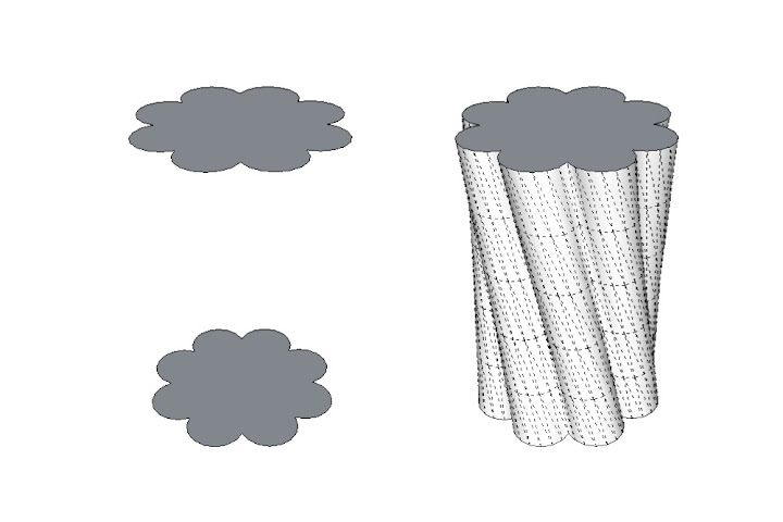
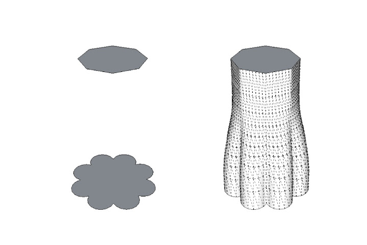
The ellipsoid “fins” that march down the length of the airplane are the key to defining the fuselage’s sleek, rounded shape.

Next, I used the maximum sheet size for the cardboard to figure out which parts would need to be subdivided and re-assembled after they’d been cut. This task was made a bit simpler by the fact that the biggest pieces of the plane—the horizontal and vertical “slabs” I’d started with—were each made up of three thicknesses of material. I just figured out a design that would hide the seams on the outside, visible layers, while allowing the middle layer pieces to overlap enough to form a strong sandwich when I glued everything together.

Parts which would ideally have been cut from a single sheet of cardboard had to be broken up into smaller pieces due to the small maximum sheet size for that material. These were then sandwiched together with glue. The resulting triple-layer laminates ended up being very stiff.

One of the last steps in the design process was to design the slots that would allow all (or at least most) of the pieces to interlock together. Figuring that the kerf (the width of the cut made by the laser) would be very small in this material, I decided to make the slots exactly as wide as the material thickness. This part was actually kind of fun—it’s the closest I’ve ever come to modeling a 3D puzzle.

There are lots of ways to cut slots in the pieces; I used the Line and Push/Pull tools in combination with the Copy and Paste in Place commands.

At this point, I began the delicate process of converting my groups into components; piece by piece, I exploded each group and then immediately made it into a component with a meaningful name. Where I had a pair of identical, flipped parts (this was actually the majority of the airplane), I made sure both were instances of the same component. The airplane is made out of 58 individual parts, but only 32 unique components.

Because the airplane is so symmetrical, most of the parts are flipped and duplicated component instances.

Just for fun, and because I knew it would look really cool, I copied the plane onto a duplicate layer, and used the Move tool to arrange the parts as though they’d been exploded out from the object’s center.

All of the airplane’s parts, exploded outward for visibility.

To have something laser cut by Ponoko, you give them a vector file (EPS or SVG) with all of the parts laid out flat. They provide Adobe Illustrator templates for all three of their standard sheet sizes, which makes things a bit easier. In order to go from a 3D, assembled object in SketchUp to a series of 2D cutting files in Illustrator, I needed to disassemble the plane piece by piece. Figuring that it would be easiest to have the assembled and flat versions adjacent to each other, I made a copy of the airplane off to the side and proceeded to take the copy apart with the Move tool. I used the Move tool’s rotation grips (and occasionally the Rotate tool) to spin pieces around so they lay flat.

I made sure not to forget any pieces by literally taking apart an assembled copy of the airplane, laying the parts flat on the ground as I proceeded.

Almost there. I drew a rectangle that matched the sheet size of the cardboard, turned it into component, and made a dozen copies. Then I went through the laborious process of figuring out how to lay out all of the airplane pieces in an efficient way. Having done some experimentation on Ponoko’s website, I’d discovered that it’s significantly cheaper to produce two copies of the same cutting file than it is to make two different sheets. Good thing, because it turns out that most of my airplane parts are symmetrical; they’re mirrored copies that exist in pairs. To take advantage of this, I arranged all of the symmetrical pieces on five sheets and produced two copies of each; all of the “singles” fit on only two more. In total, I had twelve sheets of parts.

The grey rectangles represent 31” x 15” sheets of cardboard. Notice that there are five pairs of identical parts sheets, plus only two unique sheets (in the upper left corner). This significantly reduced the laser cutting costs.

Digging around on Ponoko’s website a little more, I discovered a mention of something called “nodes” which help to keep slot-assembled parts from wobbling and falling apart. Basically, it involves adding rounded bumps to the slots in your pieces. The size, position, and number of nodes depends on your material and its thickness, and the website didn’t provide any specific tips for my double-layered corrugated cardboard, so I made an informed guess and crossed my fingers: I settled on a node height of 1/16th of an inch, which, multiplied by two, represented about a quarter of the 0.264″ thickness of the sheet. That’s a lot, but I figured that cardboard is a pretty compactible material. I was lucky; the nodes ended up working perfectly.

Nodes help to keep the parts snug when the final object is assembled.

One at a time, I copied each sheet to a new SketchUp file, set my camera to a top, parallel projection view, applied a simple, white Style with no profiles edges or other effects, did a Zoom Extents, and exported a PDF at 1:1 scale. Then I opened each PDF in Illustrator, copied just the parts, and pasted them on a new layer in the template provided by Ponoko. I went through this process a total of seven times—once for each unique sheet I’d be sending them.

The sheets are exported out of SketchUp Pro as 1:1 scale PDF files. These are then opened in a vector illustration program like Adobe Illustrator or Inkscape.

In order for Ponoko to convert an Illustrator EPS (their required upload format) into whatever file they send to their laser cutters, you need to make sure all of the edges in your drawings are colored and sized correctly. Blue lines tell the laser to cut, whereas red lines are used for engraving. Just follow the instructions on the template and you’ll be okay.

After uploading my files, putting in all my credit card details, finalizing the order, corresponding a few times with the friendly staff at Ponoko, and waiting a couple of weeks, a box arrived at my house. I opened it up and was nearly knocked over by the smell of laser-cut cardboard. It’s an odd odor; not terrible, but definitely not pleasant. I quarantined the pieces in the spare bedroom and went to work punching everything out.

The accuracy of the cutting was astounding. I’ve never laser cut anything; I expected the pieces to look good, but the quality of what I got made me alternate between grinning and literally giggling. For a person who spent hundreds of hours in architecture school hacking away at cardboard, foam core, basswood and plexiglass with an X-Acto knife, the extravagant expense of laser cutting instantly justified itself. I was hooked.

I couldn’t believe the quality of the laser-cut parts that arrived on my doorstep.

It took longer to peel the paper backing off of the individual parts than it did to assemble the actual airplane (not counting the time it took for the glue to dry completely). With only a couple of exceptions, the parts slotted together exactly the way I’d designed them to. It was the most gratifying thing I’ve made in years.

It took me only a couple of hours to put the airplane together. The next version will have less glue—that was the most time-consuming part of the process.

As a devout follower of the Church of Making Things Overcomplicated, I decided early on that the airplane should have a custom-designed instrument cluster. And a steering wheel. And a working, motorized propeller. This is already a monster blog post, so I’ll end the description of my process here. To conclude, a few photos of the end result.

The final result weighs somewhere between five and six pounds, but that includes the steering wheel, the propeller motor, and four AA batteries. My son (who’s two-and-a-half) had no trouble wearing it.
 I designed the instrument cluster entirely in LayOut, using layers of translucent details to simulate reflections, highlights and shadows.

Posted by Aidan Chopra, SketchUp Evangelist

Fabbing with friends: a WikiHouse for World Maker Faire

When we first heard about WikiHouse, we knew we wanted to build one. When WikiHouse’s co-founder gave an inspiring Ted talk this past May, we were inspired to build one. And when we read the WikiHouse modeling standards (make groups, use layers!), we knew that we just had to build one.

So as we sat down with the WikiHouse team this summer and talked about how we could collaborate for World Maker Faire, our goal was a no-brainer: design and build our own WikiHouse in just over a month.

The SketchUp WikiHouse for World Maker Faire. View more photos of this project here.

Kicking off the project, it was quickly evident that between the SketchUppers and the WikiHouse’rs, there were more than enough architects to go around. Aside from the reality that no one on the team had a CNC router in his garage, we knew we’d need a project partner with tons of CNC experience — and one who wouldn’t laugh off the idea of hammering together a thousand cut pieces in the middle of Maker Faire.

Enter our friend Bill Young over at ShopBot Tools. We’d been itching to do a project with Bill since he caught us spreading saw dust all over Maker Faire Bay Area earlier this year. Bill’s practical experience with wood selection, tolerances, and project planning are nicely measured by his ability to engrave anything (onto anything) while generally believing that most things are possible. With the right mix of optimism and practicality, we started trading SKP’s back and forth, hashing out the trade-offs in various design concepts.

Concept 1: A custom tarp could be tricky, and would we even hear ourselves over a CNC in one bay?
Concept 2: Using ‘Add location,’ we noticed the lookout would showcase a cozy stretch city highway.
Concept 3: We were charmed by an iconic design with exposed sections, but this required too much wood and time.
The Constructible Model: Just right with all the right hooks, tabs, and S-joints.

With an ‘as-built’ SketchUp model set and 160 sheets of plywood sitting in Bill’s shop, it was time to derive cutting sheets and turn up the ShopBots. (Note: if you’re looking to prep your own model for CNC, the free WikiHouse plugin for SketchUp turns grouped geometry into neatly laid out cutting sheets).

Soon after we began cutting, it became clear that our two central constraints were time and lumber. Thankfully, our design and tools were well-suited to these pressures. The WikiHouse design standards call for modular elements that could easily be added, subtracted or adapted — and because WikiHouse uses SketchUp as a platform, making in-progress changes was painless and quick. With a quick pivot for build phasing (agreeing what to cut next based on how much wood and time remained), the sawdust started blowing and the sheets started piling.

Ply piles in progress: only a small accumulation of the full project. See more photos from our cutting phase.

Some 1,150 cut pieces later, we are on our way to New York City after a fantastic month of collaboration between architects in the U.K., software engineers in Colorado, and woodworkers in Virginia. When we reach World Maker Faire, we’ll be joining forces with friends from the SketchUp community to show what open design tools, open design platforms, and a bit of courage can accomplish in just two days.

The right tools for the job: custom cut and engraved wiki-mallets for World Maker Faire.

Didn’t make it to World Maker Faire? Follow the build progress.
Want to see more photos of our project to date?
Watch a timelapse of the SketchUp WikiHouse build.

Posted by Mark Harrison on behalf of the SketchUp Team

Announcing the Visiting Professionals Program for Higher Education

In our line of work, we meet a lot of SketchUp ninjas. These people have gone way beyond memorizing keyboard shortcuts and customizing templates; they bend SketchUp Pro and LayOut to their will to solve complex design and process problems, to collaborate more efficiently with clients and partners, to build successful businesses. Frankly, these are the folks who make SketchUp do things that even we never imagined possible.

We’re inspired by these 3D experts, and we want to help transfer their expertise and knowledge to the next generation of SketchUp professionals. Our new Visiting Professionals Program is an exciting opportunity for U.S.-based university students and faculty to learn how SketchUp Pro and LayOut are used in professional practice across a variety of disciplines.

The SketchUp Pro Visiting Professionals: a veritable roster of 3D ninjas

The SketchUp Pro Visiting Professionals Program provides access to real-world experts in architecture, planning, landscape architecture, interior design, construction, video game design, film and stage design — just to name a few. Our program participants include professional designers, renowned educators, and published authors. Beyond SketchUp Pro, these are professionals who have a lot to share about managing schedules and expectations, getting client buy-in and selling project ideas, and working across multiple software platforms to develop flexible workflows. After all, for most people, getting work done means choosing the right tools and making them all work together.

Visit our program site to learn more about what a visit to your school might include, and browse our directory of professional specialists. Then, apply to have a SketchUp Visiting Professional come to your institution. We will be facilitating a limited number of no-cost, U.S. visits for the 2013-14 school year.

Posted by Allyson McDuffie, SketchUp Pro for Education, Program Manager

(re)Introducing SketchUp Make

In 2006, just a few weeks after we closed our original acquisition by Google, we introduced a slimmed-down new version of SketchUp that allowed people to quickly and easily build 3D models of the buildings that mattered to them for representation in Earth. One of the biggest features we added was actually something we took away… the price tag. This new version of SketchUp cost nothing to use—and because SketchUp is SketchUp—anyone could learn how to do so in almost no time at all.

As most folks probably now know, the free version of SketchUp has been a huge success. In the past six years or so, its user base has grown into the millions and spread around the world. Today more than 30 million people a year use SketchUp in a dozen different languages, at a rate of almost 40 starts per second. Read that again if you need minute for it to sink in… SketchUp is used almost a billion times a year. And still that number is growing.

While there are certainly communities of folks who still use SketchUp as a “geo-modeling” tool for Google Earth, the reality is that that this kind of use has only ever represented a small subset of all the things people are actually doing with it.

We found that SketchUp has been used to plan structures at Burning Man. It has also been used to launch ocean cleaning drones. Not only has it become a tool of choice for 3D printing enthusiasts, it’s been used to design the printers themselves, helping to kick off a broader revolution in personal manufacturing. On top of it all, SketchUp can be used by kids to design the best pinewood derby racers ever. Truly we’re seeing “3D for everyone” playing out at a grand scale.

SketchUp Make: Used by people who make things (sometimes even to make things that make things)

As it turns out, there’s now a name for this diversely creative and inventive group of folks who have been using SketchUp for years. We call them “Makers,” a term coined by Dale Dougherty and his gang at Make:. We’ve been a part of Dale’s movement since the beginning, and we’re in it for the long run. And it is in honor of the Maker movement that we’re re-launching our free 3D design tool under the new name “SketchUp Make.”

But really, there isn’t much else changing here—SketchUp Make is still free for non-commercial use, still powerful and still under active development. We’ve added a batch of new features to the 2013 release of SketchUp Make (check out our new STL import|export extension, for example) and we’re looking forward to developing and supporting it well into the future. Let’s go make stuff together!

Posted by John Bacus, SketchUp Team

Have questions about SketchUp Make? We’ll be listening here and on this thread in our help forum.

SketchUp Pro Story: Bob Lang, Woodworker

Robert W. Lang is executive editor of Popular Woodworking Magazine, and the author of several books including “Woodworker’s Guide to SketchUp.” Bob blogs about Woodworking and SketchUp at his website ReadWatchDo.com. We asked him to tell us a little bit about his process and why he uses SketchUp Pro.

Building furniture is a rewarding process. Most of the challenge is problem solving; time in the shop is always in short supply and quality materials aren’t cheap. Good problem solving at the start allows a more efficient build and prevents costly mistakes.

The efficiency of SketchUp means I don’t spend as much time designing and planning as I used to, which gives me more hours in the shop. Those shop hours are also better because I have a reliable reference that answers almost any question that might come up while I build. (Except for “where did I leave my pencil?”) I can concentrate on the physical work without being sidetracked with an hour or two of head scratching to solve a design or engineering problem

Early in my career, I fancied myself a designer and vowed to only create original designs. Then one day I read something from Gustav Stickley to the effect that if you wanted the ability to design new work, you needed to thoroughly understand everything that had been done before. Twenty-five years later, my work is mostly reproducing designs from the Arts & Crafts period of the early 20th century. This chair (below) is a Stickley piece, and despite its simple appearance there are a lot of subtleties to the overall design. These quirks are what make this furniture intriguing—the closer you look, the more you find.

When I’m planning a reproduction, I work a lot from photographs. My process is mainly the same one I used years ago with pencil and paper. Importing a photo, scaling it to actual size and measuring the photo on screen are far easier (and more accurate) than staring through a magnifying glass and using a proportional rule.

If possible, I work from photos I’ve taken myself; these are different than photos taken for publication. I’m looking for information, and the best source of that is a straight-on view. I’ll do some things in Photoshop, sometimes correcting for lens distortion, but mostly I adjust the image to make it easier to discern details.

After I import a picture into SketchUp, I scale it so that parts I can measure with the Tape Measure tool match known dimensions. I place the images on a separate layer, so I can easily turn them off and on as I build the model. I usually build the model near the photos, but for some parts I work on top of them. To get the outline of the corbel under the arm, I traced the shape on top of the image, then extruded it to the proper thickness with Push/Pull.

I import photos into SketchUp and scale them to a known dimension. Sometimes I model next to the photo, and sometimes I trace directly over the photo.

Sometimes the photo will reveal something I’d rather not see. The next image is from early on in the process, right before I discovered that the lower rail between the front and back legs isn’t parallel to the floor, as I have it in the model. That slight angle adds a lot to the appearance of the finished chair. It’s the chair’s way of saying “Come and have a seat!”, but it makes building the side assemblies considerably more difficult. Instead of five identical vertical slats, each one is a bit longer than its neighbor. Additionally, the shoulders of the tenons have to be cut at an angle rather than square.

With the photo available within the model for reference, I can check dimensions and details while I work. In this case I realized my first attempt missed an important but subtle detail.

Eventually, I have a model that I’m happy with; I consider this the halfway point of the process. The second half is extracting information from the model. Everything I want or need to know about every part of this chair is there on screen. Now the task is to pull out the information I need (or want to show someone else) and to put it a manageable form.

In the shop I tend to spread out until the project I’m working on covers every available horizontal surface. I follow much the same process when working in SketchUp: I make copies of the entire model (or portions of it) off in empty space somewhere to serve different functions. I create scenes for each of these views, with layers for dimensions, so I can export or print only that portion of the model. If you back up and look at everything, it’s pretty chaotic.

Zoom Extents makes it look like I’ve made a horrible mess, but I generated several scenes in a short period of time, each showing important details by copying portions of the model and moving them into empty space.

That said, each scene has a lot of value; there are a number of ways scenes can be used. In my work on books of measured drawings and for Popular Woodworking Magazine, scenes are exported to Adobe Illustrator to use for two dimensional drawings (plans, sections and elevations) or three dimensional exploded views.

This is a typical Scene that I will print and take to the shop to use as a reference for each part of a complex assembly. The model contains precise information about every part, and if I forget to print a dimension I’ll fire up the laptop, open the model for a closer look and measure the parts in the model.

For a project build video, I exported an animation of several scenes and used that clip in the finished video to explain the construction process. For my own use in the shop, I print 3D views of groups of parts and stages of the process for reference. For the side assemblies of this chair, I printed exploded views as well as details such as the image of the leg joinery. In SketchUp, it doesn’t take long to create these extra views. So far, when I wonder “Can I do this with the model?” the answer has been, “Yes I can, it works very well, and it doesn’t take very long”.

Instead of standard cutlists, I create views such as this to accurately lay out the parts. It might take 5 minutes to drag each leg out of the Components window and add dimensions, and it saves hours in the shop. It’s surprising how close this is to having real parts to refer to.

One unexpected benefit of using SketchUp is that it turns out to also be a great tool for teaching woodworking. Unlike a valuable antique, a 3D model can be taken apart to study how it goes together. When I teach a class on building a piece for real, one of the main lessons is the sequence of doing the work. This is a crucial skill for successful building; knowing which parts to layout and cut first, how those first parts affect the following parts, and how to group parts together in sub-assemblies to make the final assembly simple. With a good model, an inexperienced builder can work all of that out before getting to the shop, learn the lesson in less time and not risk wasting valuable materials or shop time. The boost in confidence from this makes a significant difference in both the quality of the time spent building and in the quality of the finished product.

Reproducing a Stickley Morris chair is a lot of work, but there is a built in reward when the job is done.

Over the last 30 years, I’ve invested a considerable amount of money in tools to do my job. A large portion of that has been spent on computer hardware and software. Looking back, the best investment has been the money I spent on SketchUp Pro. I started using SketchUp thinking it might be an effective drafting tool, but it’s turned out to be much more than that. This simple-to-use software program is the best thing I’ve found for all phases of design, engineering, planning and communicating.

Organic modeling made simple with Curviloft

The process of extruding one 2D profile such that it ends in another, different 2D profile is often called lofting. There’s no easy way to do this in plain ol’ SketchUp, but there are plenty of plugins that make it possible. The one I’ve been obsessed with lately is called Curviloft; it’s by the venerable Fredo6. If you need to learn about plugins in general, including how to install them, visit the plugins page on our website.

Curviloft lets you do three basic operations; which one you use depends on what you’re trying to accomplish. For the sake of brevity (and simplicity), I’m going to focus on only the first operation in this post: Loft By Spline.

The Basics

Let’s say you have two profiles that you want to connect together. The example below is super-simple: It’s a circle directly above a square. Here, I want to connect the two with a shape that goes directly between them. Curviloft’s Loft By Spline tool was made for just this kind of thing.

I start with two flat profiles (shapes) positioned one above the other.

Fredo6’s Curviloft plugin includes three handy tools. This post deals with the first one: Loft by Spline. To use it, you need two or more profiles. These can be closed shapes (as above) or simple, unconnected edges (see the end of this post for an example).

With nothing selected, I activate Loft By Spline and click once on each shape. Because there are only two, it doesn’t matter which shape I click first. If there were more than two, I’d click in the order that I want to connect them, starting at either end. When both profiles are numbered, I click the green checkmark in the Curviloft toolbar (see below). This brings me into Preview mode, where I can see what I’m about to end up with.

Activate the tool, then click on the profiles you’d like to use as the endpoints for the shape you’re trying to create. When you’re done, click the green checkmark to enter Preview mode.

The Curviloft toolbar is complicated; there’s no getting around it. The good news is that you don’t have to understand what all the controls do in order to use the tool. In Preview mode, you can just click things to see what happens. There’s no shame in experimentation.

The Curviloft toolbar is a doozy, but you can (and should) click buttons to see what happens. Every case is different, and some settings look better than others.

When you perform a Loft by Spline operation with Curviloft, the tool is generating two different kinds of geometry which it later combines. Intermediate profiles (left) are “in-between” 2D shapes spaced between the profiles you start out with. Splines (right) are lines that connect adjacent profiles together. They can be straight or curvy, depending on the settings you choose.

I like to fiddle with the Spline Method settings first (see below). This is where you control the shape of the vertical lines (splines) that connect the two profiles—in this case, the circle and the square. The three options that I find give the most interesting results are “Junction by connected lines”, “Bezier curves – Respect tangency (Method 2)” and “Junction by Orthogonal Bezier Curves”. By all means, try the other buttons, too; there’s gold in them thar hills.

Different settings usually produce fairly different results. Click around until you like what you see.

Playing with the Vertex Matching controls also yields some useful options (see below). Here, you’re telling Curviloft how to decide which points on the perimeter of each profile should connect to one another. In this case, the circle has 24 endpoints and the circle only has four. The tool does its best to figure out the intermediate geometry, but the Vertex Matching settings let you provide guidance. For me, the most interesting button is the one on the far right; often, deselecting “Orientate contours to their best-fit box” seems to produce better results. Click it a few times to see what happens.

To be honest, I really don’t understand what these buttons do. I have eyes, though, and I can tell what looks good and what doesn’t. I bet you can, too.

When you’re satisfied, hit Enter on your keyboard (or click the green checkmark on the toolbar) to finish generating the result.

I’m delighted every time I do one of these operations. Modeling this “by hand” would take so long that I doubt I’d even bother attempting it.


Cool variation #1: Twisting

While you’re still in Preview mode, clicking on black part of your preview object opens yet another set of controls. The Properties of the Edited Junction window shows you more information about the connections in the operation you’re doing. My favorite widgets here have to do with twisting; they let you rotate either of your profiles (in this case, the circle and the square) by 15 or 90 degree increments. The result is an insanely cool twisting effect. Click the little right and left arrows and you’ll see what I mean. Addictive, no?

Twisting 3D forms is one of those things that SketchUp modelers have resigned themselves to never being able to do. When I discovered this functionality in Curviloft, I got up and danced around.

Cool variation #2: Offset profiles

Loft by Spline works great on profiles that aren’t lined up perfectly, too. Below, I’ve moved and rotated the circle.

Your profiles don’t have to be directly on top of one another to use Loft by Spline.

Again, trying different Spline Method settings produces pretty wildly different results.

Using straight splines connects the profiles in a very direct manner. Choosing a curvy spline method produces a much jauntier shape.

I dare you not to waste an afternoon playing with Curviloft. The other two tools in the set let you loft along a path and “skin” connected profile edges, but Loft by Spline is pretty powerful on its own. Remember that Curviloft is donationware, meaning that if you like it, you can contribute to its author; you’ll find an option to do so in the Curviloft menu after you install it.

Here are some quick examples of shapes I whipped up while I was working on this post:

Both profiles are identical, but I used the twist options to spiff things up a little.

Lofting between a complex profile and a simple one can be tricky, but the smooth transition that ensues is always lovely. Rocket? Tree trunk? Bicycle handlebar grip?

Your profiles needn’t be fully-enclosed faces. Try lofting between arcs and other edges to produce all kinds of things that would be painful to model without Curviloft.

I used Curviloft to model parts of this queen I’m making. Some of us on the SketchUp team are collaborating on a 3D printed chess set.

I’ve written about a couple of Fredo6’s other terrific plugins in the past. RoundCorner gives you the ability to quickly and easily create rounds and fillets on almost any shape. FredoScale is a toolkit for stretching, bending, twisting and otherwise deforming your models in incredibly useful ways.

CustomMade: A community design marketplace

Here’s an interesting twist on our Make Ideas Real project: sometimes great designs aren’t your ideas. The good folks at CustomMade.com have developed a marketplace that connects roll-up-your-sleeve makers with people who have project ideas they want to bring to life. (Editor’s Note: CustomMade is part of the Google Ventures portfolio.) Have an idea for a one-of-a-kind armoire? On CustomMade there are about 3,000 contractors who can help you bring that idea to life.

“Kari’s Armoire,” contracted, designed and sold on CustomMade.com, Michael Colca

Of course, if you’re one of those designers and you find yourself competing with 2,999 others, affordable and efficient design software is a pretty key resource. Enter SketchUp. CustomMade’s CEO Mike Salguero recently shared a few compelling projects that were brought to life using SketchUp:

White Oak and Wenge coffee table, Jon S Manss

Sure enough, SketchUp plays a critical role in not just the design of CustomMade projects, but in the collaborative conversations between clients and artisans. Jason Hernandez, of Jason Andrew Designs, uses SketchUp to fuel the ideation and iteration process between clients and contractors: the end result, a project that both parties can buy into.

Posted by Mark Harrison, Community Manager

Message from CustomMade.com
Have you started designing your dream project with SketchUp? Post a project description on CustomMade’s “Get it Made” job board and upload .skp files as attachments. Artisans interested in building your custom project will have the chance to experience your inspiration in 3D and contact you. Let the collaboration begin!

What would you 3D print?

It’s easy to see why 3D printing has captured the imaginations of modelers around the globe — it’s captured ours as well! Being able to hold what you’ve modeled in your hand brings a new dimension (no pun intended) of understanding and usefulness to the 3D design process.

We’re curious to learn more about what SketchUp users want out of 3D printing: if you were going to (or already have!) print a SketchUp model, what would it be? Take a couple minutes to let us know.

Posted by Mark Harrison, Community Manager

Make Ideas Real: Projects for You, Projects for Me

Reviewing the hundreds of designs that SketchUp users have submitted to the Make Ideas Real project, we’ve noticed that a large number of submissions could be described as “useful.” (Shocker right? People design things for a reason!)

For some folks, “useful” means a project they’ve designed and built for their personal use. For instance, these two submissions are great examples of (small and big) personal projects modeled on SketchUp:

Bird’s Eye Maple Side Table by Chris Donaghue

Tool Shed by Gary Watson

“Useful” also means creating something of value for other people, and then actually selling it! Consider the Kapsule Lightstand, a lighting accessory for the Amazon Kindle, designed by Jonathan Hirschman of the NYC SketchUp User Group. (PS You can actually help fund this project through Kickstarter!).

Kapsule Lightstand by Jonathan Hirschman

We were also impressed by this Apple cord holder from Dean Heckler of Heckler Design:
another Kickstart project with great design, and also a great design story:

Whether you design projects for yourself or for the rest of the world, we want to see what you’ve created. If you have a SketchUp model that has become reality, add it to our Make Ideas Real collection!

Posted by Mark Harrison, Community Manager